 Final Proximity
13Kinematic test benches for rendezvous and landing
Motion you command,
sensors you Trust.
Robot arms and rails replay orbital trajectories on the ground while real cameras and lidars watch. The dynamics are computed; what is being tested is everything that senses.
T minus 00:08:00 THE IDEA
What kinematic means, and what it buys
A kinematic bench does not float anything. A real-time simulation propagates the orbital dynamics, and industrial robots impose the resulting relative motion on physical mock-ups, millimetre-accurately, while real sensors watch real surfaces under real lighting. The physics lives in the computer; the optics, the reflections, the glare and the noise are genuine.
That division of labour is the point. Contact forces and fuel slosh cannot be tested this way, but navigation can be exercised across whole approaches, repeatably, with the trajectory replayed as many times as the campaign needs. For vision-based rendezvous and landing navigation, these facilities are where the loop is closed before flight.
EPOS 2.0
DLR · OberpfaffenhofenTwo arms, one on rails
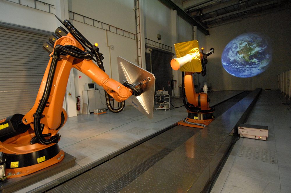
The European Proximity Operations Simulator holds two industrial robots, one riding a 25 metre rail, each carrying a mock-up or a sensor suite. A real-time dynamics simulation commands both, so the last 25 metres of an approach play out physically at true scale and true rates, hardware in the loop end to end.
Built for the DEOS servicing mission study and used ever since for rendezvous sensor qualification: the facility outlived the mission it was built for, which is the usual fate and the real value of a good bench.
TRON
DLR · BremenA dark hall with the Moon in it
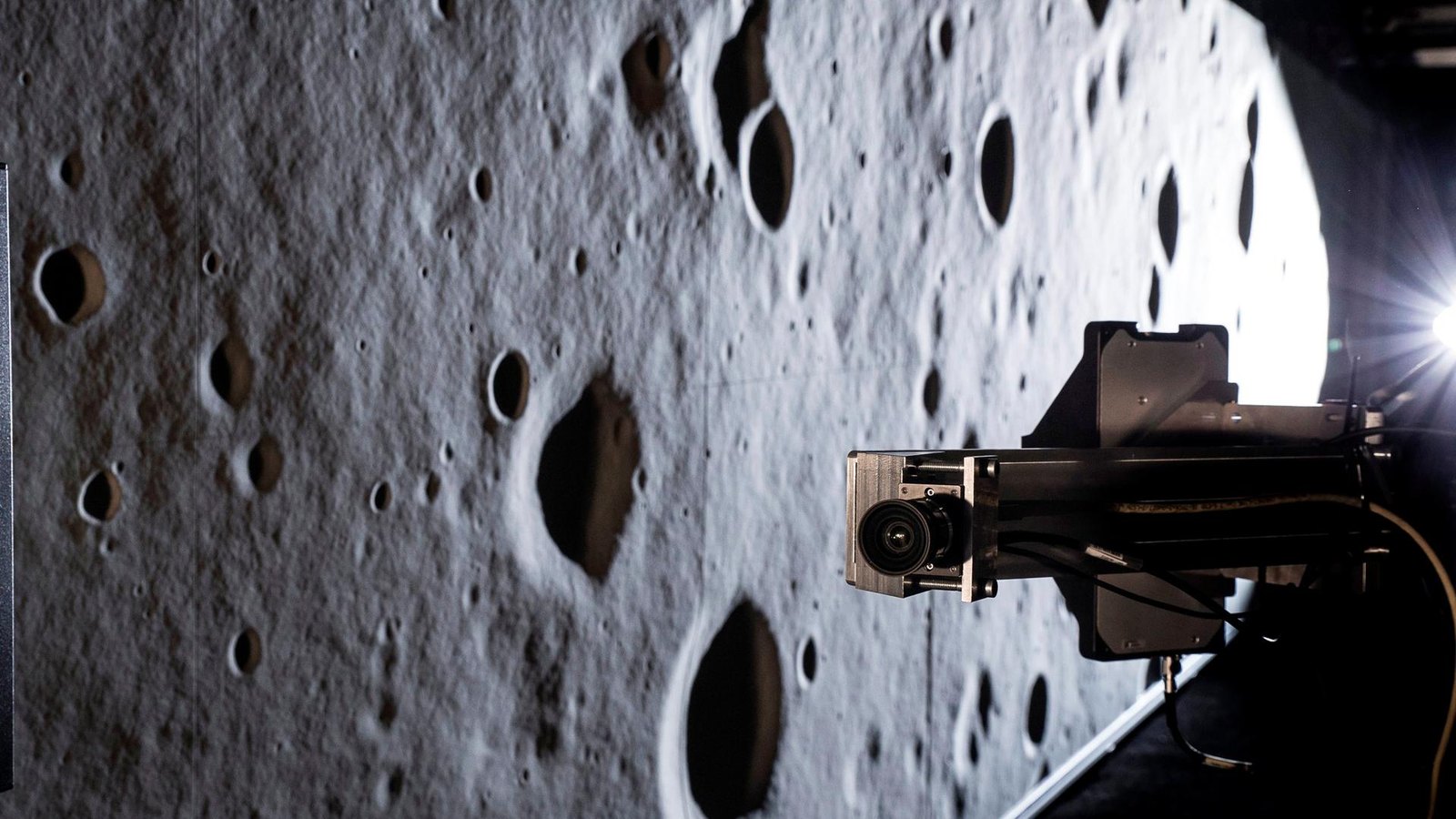
The Testbed for Robotic Optical Navigation flies a camera on a robot arm over sculpted lunar terrain in a light-sealed hall, with a sun simulator throwing the long shadows of a polar landing. Optical navigation algorithms meet cratered relief and harsh light before any of them meets the Moon.
Lighting is the quantity under test here: crater-rim shadow is what confused more than one real lander’s altimetry, and a hall where the sun angle is a dial is the only place to sweep it.
INVERITAS
DFKI RIC · BremenThe chaser flies on cables
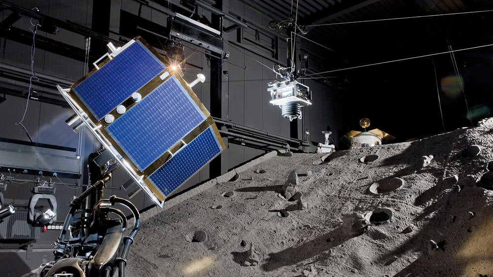
Across town from TRON, the INVERITAS facility at the DFKI Robotics Innovation Center hung a full-scale client mock-up from a cable-driven robot and gave the servicer’s sensor head to a six-axis industrial arm, nine motion degrees of freedom shared between the two systems in a hall ten metres high. Built from 2009 to 2012 with EADS Astrium and Jena-Optronik, funded through the DLR space agency, it replayed approaches from 16.5 metres down to capture range with real stereo cameras and a lidar closing the loop on an uncooperative, tumbling target.
Cables buy volume that rails cannot: a track gives precision along one line, a cable robot sweeps the whole hall, and the price is paid in stiffness and calibration rather than in concrete.
TRON
Stanford SLABRendezvous optics at university scale
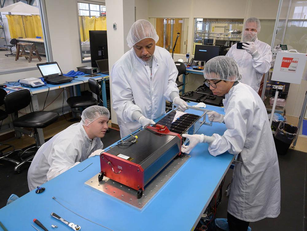
Stanford’s Testbed for Rendezvous and Optical Navigation, in the Space Rendezvous Laboratory, closes vision-based navigation loops against illuminated target mock-ups and starfields, supporting the angles-only and pose-estimation work behind missions like the Starling swarm.
The same name as DLR’s Bremen hall, coined independently for a different facility on another continent, which says something about how natural the acronym is.
Zero-G Lab
SnT · LuxembourgBoth halves in one black room
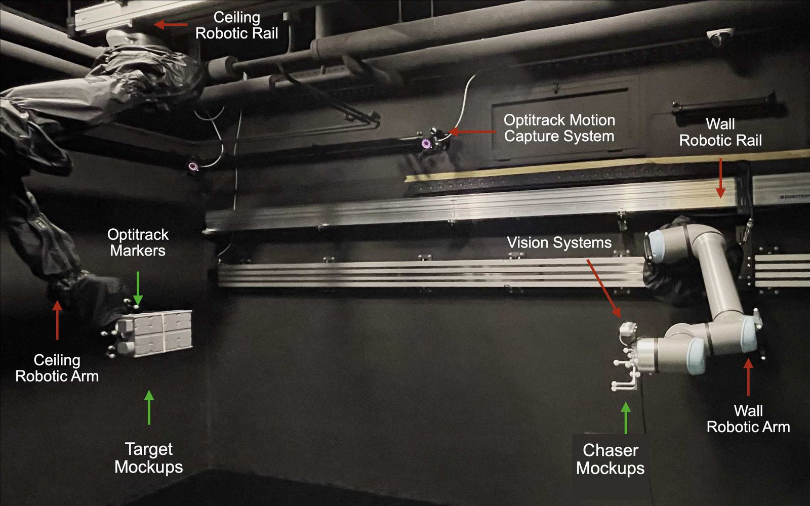
The University of Luxembourg’s Zero-G Lab paints a five by three metre room black from floor track to ceiling and hangs two UR10e arms from rails, one overhead and one on the wall, with a movable sun emulator, a motion-capture net and a super-flat epoxy floor beneath. The arms replay chaser and target trajectories for vision-based navigation work, and air-bearing platforms on the floor take over when the question turns to contact, so one small room covers both halves of the rendezvous problem.
The blackout is the optical budget: walls at black-fabric reflectance and a single controllable sun give the camera the same extreme dynamic range it will meet in orbit, which an ordinarily lit room cannot produce at any price.
GRALS
ESA · ESTECA gantry thirty metres long
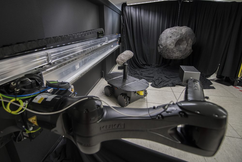
The GNC Rendezvous, Approach and Landing Simulator moves sensor heads and targets along a 33 metre track in ESTEC’s Orbital Robotics laboratory, long enough to fly the closing arc of a rendezvous or the terminal segment of a landing against physical scenery.
Scale matters in optics: some sensor behaviours only appear at real range, and a thirty metre hall is the difference between testing a camera and testing a camera at the distances it will actually work.
ROBY
Thales Alenia Space · CannesIndustrial rendezvous validation
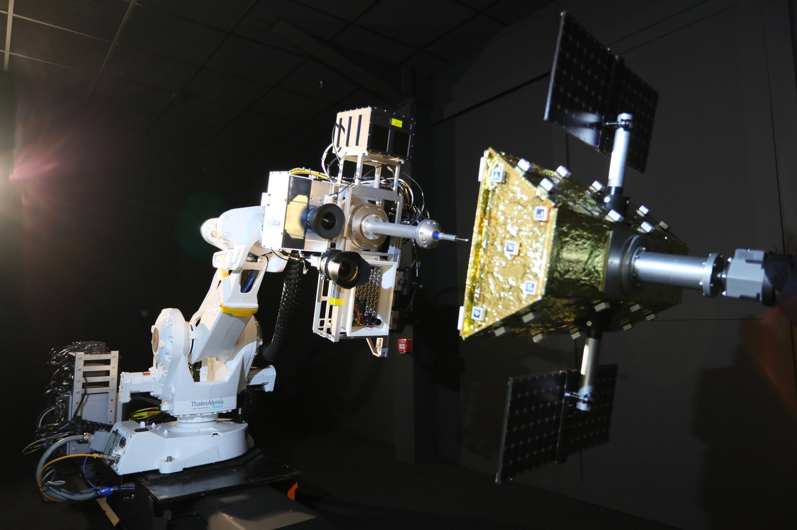
Thales Alenia’s robotic bench at Cannes replays approach trajectories for the vision systems of European rendezvous programmes, most prominently the Mars Sample Return capture work, where the target is a football-sized canister tumbling in Mars orbit.
An industrial bench earns its keep in qualification campaigns rather than research papers, which is why less is published about it than about its agency cousins; the work is the same.
platform-art©
GMV · MadridThe dance floor
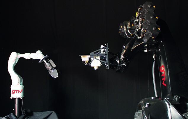
GMV’s facility combines robot arms with a moving platform across a large hall, replaying rendezvous, capture and descent trajectories for GNC validation across European servicing and exploration programmes.
Its strength is closed-loop breadth: the same floor has flown asteroid approaches, debris captures and lunar descents, because a kinematic bench does not care what mission the trajectory came from.
FREND
NRL · WashingtonGrappling the ring every satellite has
The US Naval Research Laboratory built its space robotics laboratory in 2001 to answer a DARPA question: can a robot dock with a satellite never designed to be touched? The FREND programme’s answer was a flight-class arm that tracks and grapples the launch-adapter ring nearly every spacecraft already carries, proven in autonomous grapple runs against moving mock-ups and environmental-tested for flight in 2008. The same arms and the same laboratory matured into the RSGS servicing payload now bound for geosynchronous orbit on Northrop Grumman’s Mission Robotic Vehicle.
The insight that outlived the demonstration is target selection: no cooperation, no fixtures, only a structural feature the launch vehicle already required, which is what turned one robotics project into a servicing architecture.
ROC
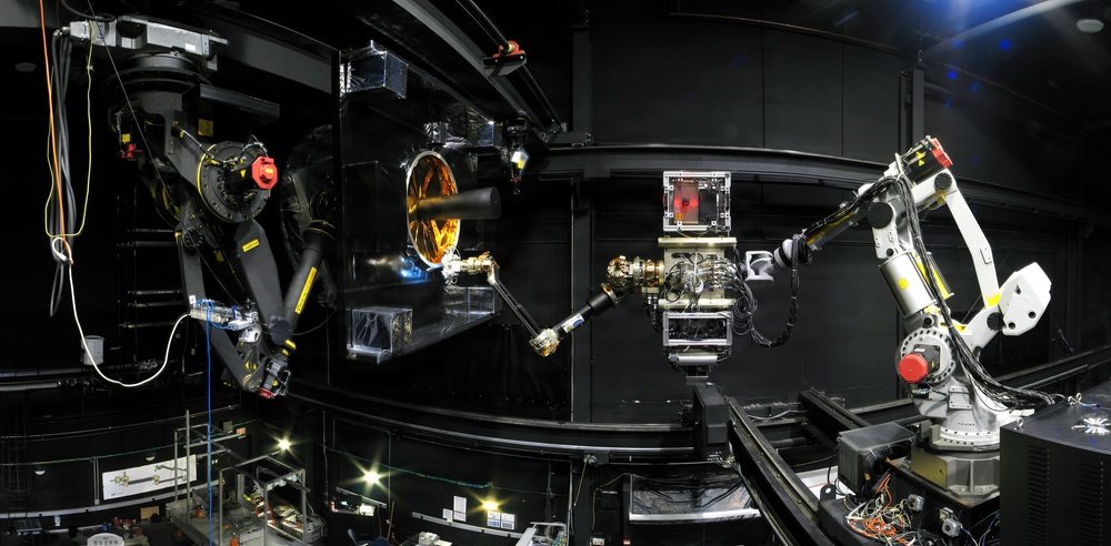
NASA · GoddardThe black-walled capture range
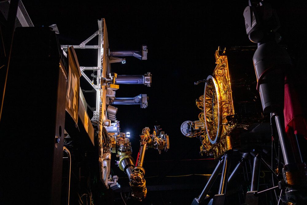
Goddard’s Robotic Operations Center wraps its arms in a black-curtained volume where servicing captures are rehearsed against full-scale mock-ups, the OSAM-1 capture sequence among them.
The black walls are not staging: stray reflections are exactly the kind of false feature a capture camera must not see, and suppressing them is part of the test design.
T minus 00:01:00 THE LIMIT
What a kinematic bench cannot tell you
Everything the robots impose is only as good as the dynamics model commanding them, and nothing here pushes back: contact forces, plume interactions and propellant slosh are exactly the effects a kinematic facility cannot produce. That is not a flaw; it is the boundary where the dynamic benches of topic 14 take over.